


Blender is a great, free - polygon / subdivision 3D drawing program / physics simulator, where almost everything can be accessed / programmed via a simple Python API.
For advanced "organic" shape design it is superior to SolidWorks. In Blender you can import STL parts designed in SolidWorks - however, SolidWorks will normally produce crappy polygons which
may be difficult to further modify in Blender. On the other side, a part designed in Blender can often be converted to NURBS by using PowerSurfacing, a SolidWork plug-in,
and then further modified in Solidworks.
Blender is not a parameter based modelling program and for "machine-like" design SolidWorks is superior to Blender.
Official help / manual
If window is messed up: Search for FILE menu - load factory settings
General subD modelling guidelines
- Geometry - Base your geometry on quads, and use as few extraordinary vertices as possible (try to obtain C2).
For each extraordinary vertex - make the deviation in order as low as possible. Never use triangular polygons in
combination with Catmull-Clark subdivision
- Flow - Getting the right flow (the way edges are drawn to resemble the main features of the shape)
is essential. A good flow can be compared to a good "design intent" in
SolidWorks. Getting the right flow requires a feeing and understanding of the fundamental features of the target shape,
and takes time to practice
- Simplicity - If a good flow is found, the target shape can be modelled by a very few polygons.
The fever polygons that is needed to convey the overall shape information / design idea, the more elegant
the design will normally be perceived.
When modelling with polygons - the trick is to first focus on the large picture/lines and not worry about details
Most used shortcuts (what is needed for INF4500)
In blender we have to modes: Object mode (top level / assembly of parts) /
edit mode (drawing inside a part)
We first add a new part in "object mode", then start modifying the part in "edit mode"
- Object mode / edit mode - toggle : "TAB"
- Tool menus - toggle : "n" / "t"
- New part - insert (in object mode) : "SPACE" - "Add" - ...
- View - rotate view : "Mmb" + "mouse move"
- View - zoom view : "mouse wheel"
- View - pan view : "SHIFT" + "Mmb" + "mouse move"
- View - align view - top / left / back :
Number pad buttons: "1" / "3" / "7"
On laptop: first enable ordinary number buttons in Blender preferences
- View - normal to selected face : "SHIFT" + "7"
- View - orthogonal / perspective toggle view : Number pad button: "5"
- View - hidden/internal items :
toggle vertex-cube button in menu under drawing canvas
- View - pivot point :
can be set to "cursor" (double white ring) by selecting this option in the menu to the right,
and cursor can then be relocated by specifying this in bottom menu "Mesh" - "Snap" - "Cursor to ..."
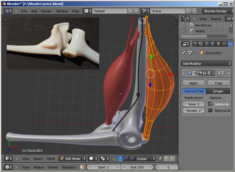
- SubSurf - add subSurf :
In the right modifier menu (spanner symbol) - "Add Modifier" - "Subdivision Surface".
In edit (drawing) mode:
- Select - toggle select / deselect all : "a"
- Select - single vertex / edge / face :
- Select : vertex-symbol / line-symbol / face-symbol, in the menu under the drawing canvas
- "Rmb" on the item in the canvas
- Select - add new item to the selection :
"SHIFT" + "Rmb" the new item
- Select - add region/area of items to the selection :
"CTR" + "Lmb" + "mouse move"
- Move - selected vertex / edge / face in current SCREEN xy direction:
"Rmb" + "mouse move"
- Move - selected vertex / edge / face in ABSOLUTE xyz
direction: while moving press "x" / "y" / "z"
- Extrude - face : "Select the face" + "e" + "mouse move"
- Extrude - edge : "Select the edge" + "e" + "mouse move"
- Extrude - vertex : "Select the vertex" + "e" + "mouse move"
- Extrude - edge / face / vertex in x / y / z direction :
"Select the item" + "e" + "x" / "y" / "z" + "mouse move"
- Adding - an edge in between to vertices :
"Select the two vertices" - "f"
- Adding - a face in between to edges :
"Select the two edges" + "f"
- Manually subdividing the interior of a single polygon :
"Select the polygon" - "e" - "ENTER" - "s" - "mouse move"
- Delete - edge / face / vertex : "Select item" + "Delete"
- Edge loop - add edge loop
: "Select edge modus (line)" + "place mouse over crossing edge" + "CTR" + "r" + "mouse move"
- Edge loop - select edge loop :
"place mouse over an edge in the loop" - "SHIFT" + "ALT" + "Rmb"
- Face loop - select face loop :
"place mouse over a face in the loop" - "SHIFT" + "ALT" + "Rmb"
- Scale - selection : "s" + ["x/y/z"] + "mouse move" + "ENTER".
By entering the number 0, vertices can be scaled to zero in the selected direction (flat)
- Rotate - selection : "r" + ["x/y/z"] + "mouse move" + "ENTER".
- Mirror - all items in x direction : Add mirror modifier (spanner tool).
Both halves may be joined by adjusting "Merge limit". The mirrored halve can be permanently created by the "Apply"
button. If subdivision modifier is used, it
must be arranged after the mirror modifier
- OBJ export for import into SolidWorks (PowerSurfacing) :
in object mode - select all, "a" - export as OBJ. Do NOT export subdivision surfaces - these will be
re-generated in SolidWorks
Extra
- Smooth vertices : Sometimes it is necessary to smooth out a part
of the mesh. Select the vertices - press the "Smooth vertex" button in the left "Mesh Tools" menu several times.
- Hide / Show lower lower editing panel : "SHIFT"+"SPACE"
- STL export for 3D printing :
in object mode - select all, "a" - export as STL. Units can be chosen as mm on the printer
- Fix wrong normals : select all,
"a" - menu: "Mesh" - "Normals" - "Recalculate"
- Colour/texture :
can be set in the "material menu" to the right